My first day roving on Mars

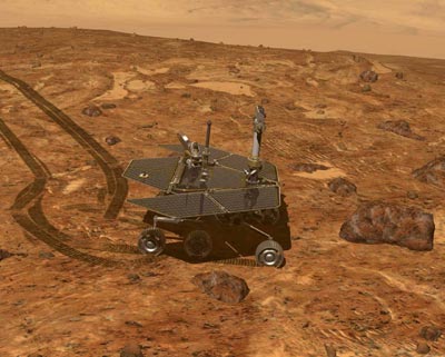
I recently joined the Mars Exploration Rover team as a TAP/SIE (Tactical Activity Planner / Sequence Integration Engineer) for the Opportunity rover. That means it’s my job to sit in on the morning SOWG (Science Operations Working Group) meeting, in which the rover’s scientific goals for the day are set, and then work with payload, thermal, downlink, mobility, and other experts to come up with a plan to achieve those goals. What pictures will we take? When? Where will we drive? Is there enough power?

Reading the training documents only gets you so far. I’ve just begun “shadowing” the current TAP/SIEs so that I can learn on the job, watching over their shoulders through a day of planning. My first shift was on Wednesday, and it was supposed to be an “easy” day: pick one of two rock targets, drive towards it, and take some pictures looking backward at yesterday’s tracks.

Scientists dialed in from all over the country for the SOWG meeting. After some debate and consultation with the Rover Planners, they settled on the rock that had the easiest approach. The scientists signed off and we went to work building the plan.

The TAP/SIE’s job is facilitated by a bewildering array of scripts and tools. These allow for the setup, development, refinement, and checking of the plan. Are power or thermal constraints violated? Do we have enough onboard storage space for the new images to be collected and enough downlink allocation to get them back to Earth?

While the RPs (Rover Planners) settled in to their job of constructing the drive sequence, we worked on the full sol’s plan (a day on Mars, which is 24 hours and 40 minutes in Earth time, is called a sol). Very quickly we realized that the planned drive, despite covering only a couple of meters, would drain the rover’s battery dangerously low. Opportunity was starting the sol at only 80% charge because of two long instrument observations the previous sol.

We modified the plan to give the rover a morning “nap” in which it could sun itself and collect power, like a desert lizard. That helped the power situation, but not enough. Several iterations later, we finally squeaked by at 0.1 Amp-hour above the required threshold.

Meanwhile, the RPs were growing concerned about a different problem. To reach its goal, Opportunity would have to straddle a rock that, while small by human standards, could pose a risk to the rover’s instrument arm, which dangles slightly down when stowed for driving. The RPs put their 3D simulation of the rover and the terrain up for all to see, and we stared at the screen while they spun the rover and tried to examine the rock from all angles.

“Can we raise the arm while it drives over the rock?” I whispered to the TAP/SIE I was shadowing. “It’s risky to do that,” she whispered back. “The arm bobs around, especially going over a big rock.”

A few minutes later, a scientist on the telecon asked, “Can’t we just put the arm up?” but was quickly shot down by the TUL (Tactical Uplink Lead, head planner): “Too risky.” The TAP/SIE and I grinned at each other.

Ultimately, it was deemed too dangeous to drive over the rock with our current data (images the rover had taken the sol before), and they decided to drive up to that rock and stop. Post-drive imaging would illuminate the obstacle in more detail.

At the end of our shift, which apparently was two hours later than usual, we had a plan. We ran it through multiple checks and re-checks and manually confirmed all of the sequences. The final walk-through was punctuated with “check!” coming from different areas of the room as each person confirmed that their part was correctly represented. The plan was finalized and transmitted to the rover using the Deep Space Network later that night.

There’s nothing like seeing a job in action. I learned a lot about the steps involved in planning and (unexpectedly) a lot of re-planning. For the rover, today is “tosol” and yesterday is “yestersol.” I got to practice the phonetic alphabet, which is used to communicate letters (in rover sequence ids) with a minimal chance that they will be misheard. I even got to help out a bit as a second pair of eyes to catch typos, spot constraint violations, and suggest alternative solutions. And I’ll be back on shift next Monday!

Opportunity is near Endeavor Crater, working its way along a ridge that is at the perfect tilt to keep its solar arrays pointed toward the sun. This is important because Winter Is Coming, even on Mars, and we want to keep it sufficiently powered to make it through to spring — its fifth spring on Mars. (Opportunity landed 9.5 Earth years ago!)

Radiant barrier plywood works!

When the contractor tore off my old shingles to replace my roof, they found that underneath were the original wooden shingles. California code no longer permits wooden shingles (fire hazard!), so these had to come off, too. But the wooden shingles were laid on slats with 6-inch gaps between them, so that meant I also needed a layer of plywood put down to support the new shingles. California code (at least in my town) also requires that this plywood be radiant barrier plywood, which is plywood with a foil backing on one side. You lay the plywood shiny-side *down*, and then in theory it reflects heat back up through the shingles, reducing what gets into the attic.

My contractor was skeptical as to whether this plywood would really make a difference, but agreed to install it per code. (It is also not much more expensive than regular plywood.) Naturally, I wanted to test it empirically. So I collected some data.

My SCE smart meter reports the maximum daily temperature and my energy consumption per hour online. I have my thermostat set to 85 F during the day, and I can track when the air conditioner came on by looking for a spike in energy consumption. I defined the hour at which the A/C came on (i.e., internal house temperature reached 85 F) as an hourly consumption greater than 1 kWh. In the following plot, I show the time when the A/C came on as a function of maximum outside temperature. Higher values are better (later in the day). And sure enough, the new roof out-performs the old one.

Note that I used a linear fit here, but that probably isn’t appropriate at higher temperatures. Also, the times are capped at 18:00 (6 p.m.) as that’s when my thermostat switches to “evening” mode and tries to drive the temperature down to 82 F instead of 85 F.

Caveats: this is the result of the roof as a package, not just the plywood. I also had attic vents installed that probably help keep the attic cooler. It’s also possible that I’m seeing more of an effect than others might, because as far as I can tell my house has no insulation in the ceiling (California!). Thus, the living space and attic are more coupled than they would be with insulation.

Overall, however, I’m pleased to see that my new roof is performing so well! The only down side of the radiant barrier plywood is that it came with an intense chemical smell that soaked down through the attic into the living space and, on hot days, was so bad that I had to turn off the A/C so I could open the windows and tough out the heat just to be able to breathe. I couldn’t access the attic at all. Happily, after about three weeks, this finally faded away. The manufacturer claims this is due to the glue in the plywood.

Ticking mechanics

I love fixing things. So imagine my delight when today I finally tore open a wall clock that stopped running years ago and got it working again. This clock has been stopped for so long that I’ve lost the habit of even looking at it, yet I’m so fond of the thing that I haven’t had the heart to replace it. (It was one of the first decorations I added to my first grad school apartment.) I’d previously given up when replacing the battery didn’t do the trick.

This clock has a simple time piece stuck to the back of it. I examined its mount and then carefully pried it off, at which point the hands fell off their spindle and clattered to the bottom of the front of the clock (it has a plastic enclosure). I couldn’t tell if that had destroyed anything, but since I had nothing to lose, I pressed on. I pried the time piece apart so I could get at the inside, which featured a bunch of flimsy plastic gears, a tightly wound spool of copper wire, and a tiny circuit board. I pried this up to see the circuit board, at which point the gears exploded off their mounts and went flying.

Nothing seemed obviously fried or broken with the circuit board, so I decided to try reassembling it. Because I hadn’t taken a picture of their arrangement, I then spent several minutes puzzling out the mechanical logic of the seven (!) interlocking gears (two are underneath in this shot). This is not the correct solution. This is the picture I took after reassembling them the first time (which I thought was correct). Everything fit together, and it started ticking (hooray!), and the little gears all started turning at different rates. But right after taking this picture, when I snapped the case on top, I heard a SNAP and then a little rattle when I moved the case. I was sure I’d broken some vital plastic bit. I opened it back up and found that one of the plastic stand-offs was broken. However, it didn’t seem vital, so I pressed on. The rightmost gear in this shot is the one that’s wrong. I finally figured out that it goes underneath the platform (it’s the gear that lets you manually set the time). The gear that drives the ticking is on the far left.

Encouraged, I snapped the case on, and it was still ticking. I then disassembled the front of the clock to get at the hands. I mounted the time piece to the back of the clock frame, took the battery out (it stopped ticking), stuck the three clock hands on the spindle axis in the correct order, and set them to point at 12:00:00. I twisted the dial to manually set the time, stuck the battery back in, and IT WORKED!

So basically, I didn’t learn anything about what was wrong or how to fix it, except that (as sometimes happens), just taking the thing apart and putting it back together did the trick. The fun part was figuring out how to get in, and then how to fit everything together. It’s possible that some dust had wedged in there or some of the tiny gears were just slightly not touching or the battery leads weren’t making the right contact. I favor the latter hypothesis since I couldn’t hear any ticking. But either way, it works now!

How Swiss Army knives and thermometers are made

Ever wondered how a Swiss Army knife is put together? Wonder no more!

This is just one of a whole pile of fascinating “How It’s Made” videos put out by the Science Channel. Here’s another great one about how thermometers are made:


In these thermometers, they use an unspecified blue liquid (to avoid toxic mercury) that expands and contracts with temperature. The calibration process is fascinating (and surprisingly manual).

I’m already having trouble dragging myself away from this site! Enjoy!

Kinematics and engineering

OSU offers a course called ME 412: Design of Mechanisms. Sadly, it is only offered during the winter term, and I am here for the fall term. So I contacted the professor to find out more about what sort of books and other materials the course uses, for my own investigation. Imagine my delight when he gave me a copy of the latest edition of the textbook and sent me on my way!

This textbook, Design of Machinery, may well be the best textbook I’ve ever read. Really. Unlike some books that pay lip service to being clear and accessible, this text really is clear and accessible. It is also annotated with lots of amusing cartoons and very clearly illustrated examples — the latter being crucial since we’re talking about physical devices and how they move. The book comes with a DVD with animations that I haven’t been able to play with, since it is Windows-only. But, of course, there are linkage animations galore online. And even better is building them yourself, physically.

Chapter 1, “Kinematics of Mechanisms,” is charmingly written and touches on the broader subject of what it means to be an engineer, and how one of the biggest challenges is learning how to “structure the unstructured problem” to go from a concept to a problem definition to a solution. One tip the book offers is to use “functional visualization” (meaning, focus on the desired behavior of the solution, but no one kind of “embodiment”) so as not to limit your creativity and be restricted by a specific kind of solution early on. It also encourages you to make cardboard models of linkages that you design (as above) — a philosophy I think makes a lot of sense.

The chapter also includes the text from a paper given by George A. Wood Jr. titled “Educating for Creativity in Engineering.” Two of my favorite quotes from the paper are, “To me, the creative moment is the greatest reward that the profession of engineering gives,” and “If a person decides to be a designer, his training should instill in him a continuing curiosity to know how each machine he sees works.” Yes! Yes!

On a more concrete level, I learned that kinematics is “the study of motion without regard to forces,” while kinetics is “the study of forces on systems in motion.” The first half of this book focuses on kinematics, reserving forces for the second half. I can already tell that kinematics alone provides ample material to keep me busy!

“Once you become familiar with the terms and principles of kinematics, you will no longer be able to look at any machine or product without seeing its kinematic aspects.”

It’s already happened. At a conference last week, after ironing a shirt in my hotel room, I sat down and drew my first kinematics diagram — of the ironing board.

I’ve already started working through Chapter 2, “Kinematics Fundamentals,” which is fascinating but slower going, as it’s dense with new information, terms, and concepts for me. But I’m already impatient to get to the end of this chapter, where there are 15 pages of problems to do! Starting with… drawing kinematics diagrams of familiar objects like ironing boards. Ooops, jumped the gun on that one!

« Newer entries · Older entries »