January 5th, 2010 at 10:06 pm (Engineering, Spacecraft)
Tonight I was lucky enough to get to watch the International Space Station fly by: a bright unwinking point arcing upward and then, just past zenith, disappearing as it passed into the Earth’s shadow. This sight somehow never fails to stir something inside me. It is one thing to read news articles about spacecraft in orbit, and quite another to see them with your own eyes. Beyond that, the ISS marks our ability specifically to maintain a human presence in space—quite a bold and amazing feat, no matter how many years have passed since the Apollo missions.
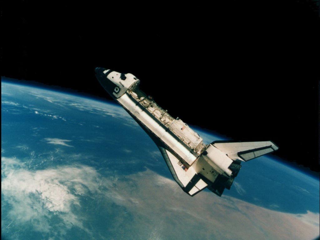 One way that we get humans (and equipment, supplies, etc.) from the ground and up to the ISS is via the Space Shuttle. The Shuttle is a marvel of engineering—perhaps too much of a marvel, rendering it less reliable than we might hope—and it is in the sunset of its career. 2010 will see the final Shuttle flights (just five more are planned), and then the Shuttle will be retired while effort and funds are focused instead on developing its successor, the Orion spacecraft. During the 5+-year gap between the Shuttle’s retirement and the first crewed Orion flights, we will rely on the Russian Soyuz spacecraft to reach and resupply the ISS.
There are many fascinating engineering details about the Shuttle and how it works. I recently came across one that really surprised me. It turns out that when the Shuttle de-orbits and descends through the Earth’s atmosphere to land, it manages that whole long glide and deceleration without any engine power. Effectively, it aerobrakes (taking advantage of our thick atmosphere), and attitude control is maintained through thrusters and hydraulically actuated surfaces. This isn’t enough to slow it all the way down, so the Shuttle also executes several S-shaped swoops to the left and right, dissipating speed horizontally instead of vertically.
You can watch a Shuttle landing from the cockpit view (STS-98): fascinating, although I guess the video starts after the four swooping banks have already been done. The dramatic right turn you see in the video is the commander’s final lineup with the runway—a final turn that also reduces speed and altitude.
The next shuttle to launch will be Endeavor (STS-130), on February 7. It will be the 32nd shuttle mission to the ISS.
2 Comments
1 of 2 people learned something from this entry.
January 2nd, 2010 at 6:43 pm (Engineering, MDRS)
1 Comments
1 of 1 people learned something from this entry.
November 17th, 2009 at 11:10 pm (Books, Engineering, Technology)
In reading “The How and Why of Mechanical Movements,” I’ve gone from levers to linkages to wheels to pulleys to screws, plus a really fascinating discussion of friction and its use in machines. One of the cleverest devices I’ve seen so far is the differential pulley or differential hoist, used in auto repair shops and factories to allow humans to lift very heavy loads (like car engines).
 The differential pulley is composed of two pulleys with different diameters mounted on the same axle. The rope (or chain, with toothed pulleys, to prevent slippage) is looped in opposite directions over the two pulleys, with the weight to be lifted suspend from one downward loop. If you pull on the other (unloaded) loop hanging down, relative to the larger-diameter pulley, then for each meter of rope/chain it releases, the smaller pulley must take up fractionally more rope/chain, yielding a net lift for the suspended weight. The diameter difference means that you had to pull more rope/chain than the distance the weight was lifted, yielding a mechanical advantage (i.e., you don’t have to pull as hard, you just have to do it for longer). This is difficult to explain in words, and much easier to grasp from a diagram; click the image at right to enlarge it. (I personally found the differential windlass, which was a precursor to the differential hoist, a useful aid in understanding the latter.) At first it seems counter-intuitive that the weight should hang suspended without pulling the second loop tight as well, until you observe that the key is that the two pulleys share the same axle and are wound in different directions. Thus the weight pulls equally on both sides of the axle and it does not turn, until an additional force (your hand) upsets that balance. (All drawings are from A First Course in Physics, by Robert Andrews Millikan and Henry Gordon Gale (Ginn and Company, 1906), as cited in Donald Simanek’s lecture on simple machines.)
If it wasn’t obvious, I’m really enjoying this book (and learning a lot). The current chapter just covered automobile clutches and brakes and several different kinds of bearings. The next chapter moves on to gears and transmissions (actual automobile transmissions, manual and automatic). Given its richness and re-read value, I’m likely to want to keep this one much longer than the library permits. Amazon to the rescue!
2 Comments
2 of 2 people learned something from this entry.
October 27th, 2009 at 10:45 pm (Books, Engineering, Technology)
It’s easy to get something to move in a circle; just pin one end down and rotate the rest (like the kind of compass you draw with) or pin the center down and rotate (like a merry-go-round). But how do you get something to move in a perfectly straight line, as is needed, for example, in engines with pistons? I’m reading a delightful book from the 1960’s called “The How and Why of Mechanical Movements,” and the subject of straight-line motion came up in chapter 2 (Levers).
It turns out that a clever arrangement of a collection of rigid bars, connected into a linkage, can give you this magical straight-line motion. Various inspired inventors have come up with different ways to achieve it, and their concepts are illuminating and fascinating.
 There’s Watt’s linkage, which requires only three links. It doesn’t quite produce perfectly straight motion (note path of the red point in the animation at right), but good enough that it was used by early steam engines. It’s still used in the rear axle suspension of some vehicles, so that no sideways motion is permitted between the body of the car and the axle (the axle only moves in a vertical straight line with respect to the car body).
The Chebyshev linkage (below left) likewise uses three links and achieves a straighter line, within a prescribed range. In 1864, the Peaucellier-Lipkin linkage (below right) was invented, and it even comes with a proof of collinearity. (These animations are awesome!)
The authors of “How Round is Your Circle?” (another book that looks absolutely engrossing) have an excellent supplementary website. One page shows some beautiful physical incarnations of the almost-straight-line linkages as well as the truly straight-line linkages (check out the videos!).
And now, I’m off to read about more fabulous mechanical movements and be awed by others’ ingenuity.
2 Comments
2 of 2 people learned something from this entry.


