First transatlantic flight

Recently I got to visit the site of the first transatlantic flight’s landing – in Ireland. The June 1919 flight was achieved by John Alcock and Arthur Brown in a biplane.

These were two interesting aviators! They were both pilots during WWI (although not together), and they were both taken prisoner (Alcock in Turkey, Brown in Germany) and then (presumably) released. Alcock approached an airplane company called Vickers to suggest that he fly their Vickers Vimy IV bomber in the race to see who would be the first to cross the Atlantic. Brown joined up later and due to his exceptional navigational skills was chosen to fly with Alcock.

The 16-hour flight itself sounds pretty harrowing. They departed Newfoundland at 1:45 p.m. They had several equipment problems including the loss of their radio, intercom, and heating. They were flying in a biplane with two open-cockpit seats! Bad weather meant Brown couldn’t use his sextant to help them steer from 5 p.m. until midnight. Happily, they still made it to Clifden, Ireland, and ended up landing next to Marconi’s transatlantic wireless station (an excellent visual landmark). Unfortunately, they thought they spotted a stretch of open ground to land on that turned out to be a bog, so when the plane landed and slowed, it sank nose-in. They escaped unhurt but the plane was damaged. Still, heroes who won the 10,000-pound prize!

From Wikipedia, this appears to be an actual photo taken after landing:

They also carried a small mailbag so they could count their flight as the first transatlantic airmail flight :)

As usual, I am awed by the courage and daring of early aviators!

The Art of Getting There

Today I had the pleasure of visiting the Pasadena Museum of History. I went to check out their exhibit on railroad-inspired art. It was delightful! Among other things, several of the pieces were inspired by the very steam locomotive that I got to operate a few weeks ago (see art at right!), as well as other engines and people from the Nevada Northern Railway.

One artist whose work I enjoyed was Bradford Salamon. The first item in the gallery is a dynamic locomotive he painted (titled “Unknown Adventures”), which sadly I cannot find online or on his website to share with you (and photos were not permitted). It was accompanied by a charming statement describing how he enjoys painting “portraits” of objects, not to reproduce the objects, but instead to trigger a memory or feeling associated with them. He paints typewriters, phones, radios, cars, … and trains. Here is one of his trains that I was able to find:

There were also several woodblock prints from Japan that were commissioned to get the public excited when trains were first introduced in Japan (~1850s). Because they were commissioned before the trains actually arrived, and none of the artists had ever seen one, they often copied from U.S. or British publications that showed steam engines… and in one case a steam fire-engine (to put fires out)!

One artist copied from a picture of a train on the Panama Railway, in which one car had “U.S. Mail” printed on it; in the Japanese version, this became “U.S. Maus” (‘maus’ happens to be ‘mouse’ in German). The gallery showed the source images that the artists had used, and you could definitely see how “Mail” could be misinterpreted as “Maus” if you did not speak English!

Here is the Panama original (but not at high enough resolution to read the relevant letters):

Now I want to ride the Panama Railway! You can – it’s a one-hour ride that costs only $25, and includes an open-air viewing deck! Time for a trip to Panama? :)

How to drive a steam locomotive

I recently got to drive a steam locomotive! The Nevada Northern Railway in Ely, NV, allows you to Be the Engineer for a 14-mile trip up and down hills, through two tunnels, and across several road crossings. This is an incredible experience – visually and physically!

(By the way – I learned that you “run” or “operate” an engine, not “drive” it, since no steering is involved. But that is how they describe the experience to newcomers :) )

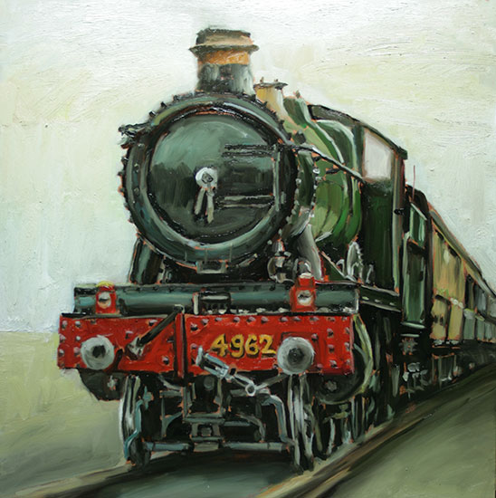
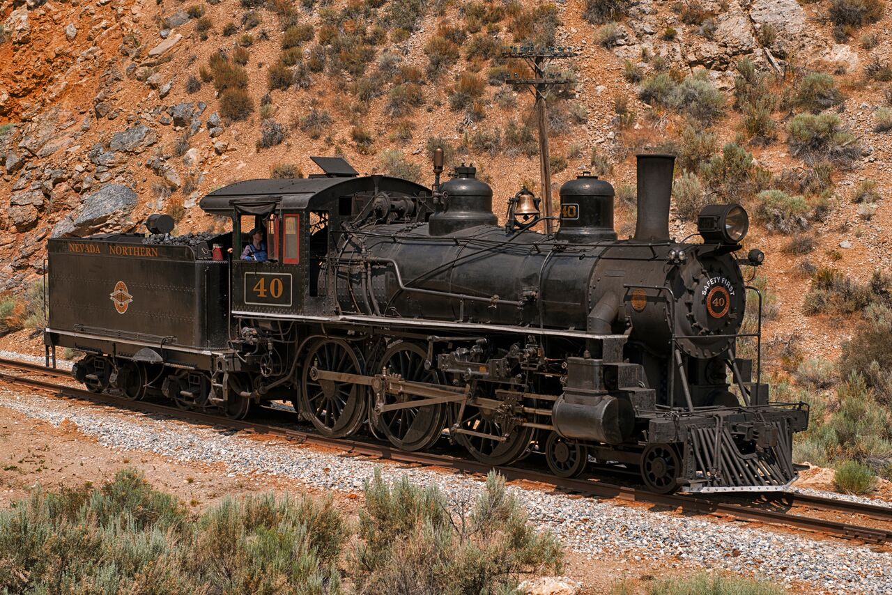
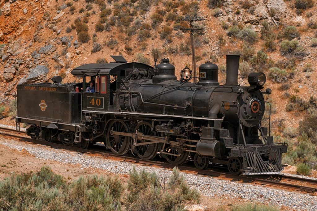
Did you ever see such a beautiful engine?


NN 40, built by Baldwin in 1910

Before climbing into the engineer’s seat, I had to study a 122-page rulebook and take a short (open book) exam. I learned about whistle signals, hand signals, speed limits, track warrants, air brakes, and more. I learned radio protocol (interestingly, it’s backwards from typical airplane conventions; you announce who you are and then who you want to speak with, e.g., “NN 93 to NN Conductor 93, over”). In addition, “the use of ten codes” (I assume this means things like “10-4”) is prohibited.

I also helped get the engine ready for action. The rest of the crew gave me small jobs, like greasing the many bolts that connect rods and other pieces, and refilling the oil reservoirs. Meanwhile, they stoked up the fire in the boiler, cleaned the engine, filled up the tender’s 6000-gallon water tank, and ensured we had enough coal. The steam engine goes through 75 gallons of water *per mile* and consumes about a ton of coal in the 14-mile trip we did!

After three hours of prep, the engine was ready to go! I climbed up into the cab and learned how to start and stop the engine, then practiced this while we were still in the railyard.

The primary controls are the throttle and the brake. The throttle is a squeeze lever with many (~20) detents. Bouncing along, it requires some fine eye-hand coordination to move it precisely to the desired notch. It, too, is backwards from the throttle on an airplane: moving it out (towards you) gives you more steam, not less!

The brake is a smaller handle, easier to manipulate. If you want to slow down, you move it to a setting that allows compressed air into the brake cylinders, pressing the brake shoes against the wheels. You monitor how much brake you are applying through a pressure gauge. Then you move the handle the other direction to release the compressed air (you can hear it hiss out) and the wheels resume unimpeded motion.

The massive locomotive responds slowly to control changes, so both controls are best applied with careful anticipation of the upcoming track – its grade, any curves, preparation for tunnels, etc.

There is also a reversing lever that is mounted vertically in the floor. As one of my books warns, “A strong arm is needed for the reversing lever!” It has a more subtle effect on locomotion by altering the amount of steam that gets into the piston cylinders on each stroke. You want it set full forward to get moving, then back it off for “cruise” to achieve more efficient operations.

And we were off! We left the railyard and climbed a gentle hill. We went through two tunnels and several road crossings. For each crossing, I blew the whistle – LONG LONG short LONG! Mike, our fireman, was busy shoveling coal as needed, injecting more water into the boiler, and ringing the bell through all crossings as well. What a delightful noise!

We used a GPS-based speedometer to track our speed, which stopped working each time we went into a tunnel. However, after a while you get a feel for speed based on the sound of the pistons (and such a lovely sound it is). Pistons mounted on each side provide the driving power for the large wheels. Each wheel gets driven twice per rotation (unlike engines in cars, airplanes, etc.):


In addition, the left and right wheels are offset in phase so that one side gets maximal torque when the other is at minimum (end of its stroke). So what you hear is CHUFF-chuff-chuff-chuff as the pistons go right-forward, left-forward, right-back, left-back, for a smooth continuous overall motion.

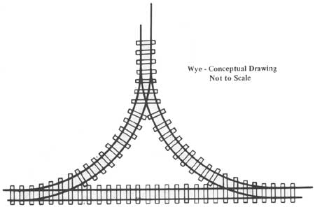
At the top of the hill, I gave the controls over to John, the engineer who was training me, and he traced our way through a “wye” (track set up to enable a three-point turn by an engine), which got us set up to return back downhill.

We then continued back down the hill to return to the railyard. The whole trip took about an hour and 15 minutes. After the initial learning curve, it got very comfortable to roll along and listen and respond to the chuff of the pistons as needed. My mind quieted and I filled up with the pure joy of the moment. What an overwhelming experience!


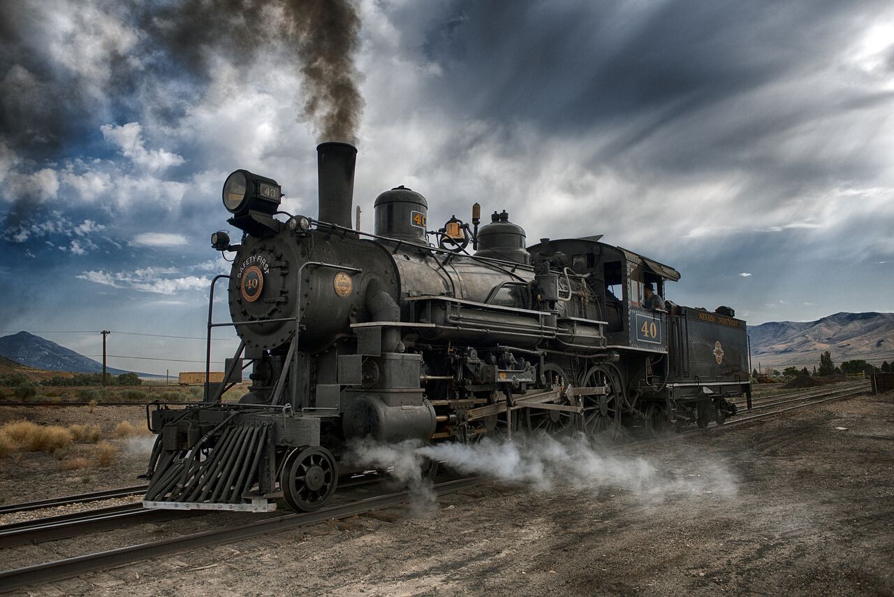
Me driving Number 40

Thank you to Richard Ondrovic for taking these fantastic photos!

A new use for human corpses

Here’s a neat idea – use composting techniques to take care of our own dead bodies.

In this TED talk, Katrina Spade makes a compelling argument for a new way of managing the corpse part of dying. I’ve long been a fan of cremation over burial, for the reasons she explains, but she also makes good points about the downside of how cremation consumes a lot of energy and generates, effectively, human ash pollution.

The idea of “re-composing” bodies, in ways that allow your molecules to be broken down and eventually used to nurture new life, is refreshing! I also like the idea that bereaved family and friends can have whatever kind of ceremony they like as part of the send-off of the body. For those who like to visit gravesites in remembrance of those who are gone, why not designate a location of positive memories with the deceased (a favorite beach or park, or the site of a graduation or wedding proposal or other significant event), or even have a shrine set aside inside the home (I’ve always liked this idea anyway).

Wired wrote an article about this last year that contains some diagrams about how the envisioned recomposition center would look and operate: Inside the Machine that will turn your Corpse into Compost

And for the current status of the project, check out Urban Death Project (a slightly more creepy name than “Urban Recomposer” or other alternatives). They already demonstrated success in composting six cadavers, and it looks like they are starting the next pilot project this month. This will be fascinating to follow!

Pick your prime meridian

On Earth, the line of zero degrees longitude runs through Greenwich, England. What about other planets?

Unlike latitude, longitude has no physically defined starting point. Zero degrees of latitude is at a planet’s equator and is easy to establish from the body’s rotation (although as noted by Wikipedia, technically it also depends on the “reference ellipsoid” chosen to model the body). In contrast, zero degrees of longitude can be wherever you want it to be. However, change it with caution: any modifications mean that all of your previous maps and published locations have to be updated!

This happened on Mars. Originally (1830), the line of zero degrees was set to be a point in a dark region that was 40 years later named (due to its utility) Sinus Meridiani (get it?).

In 1969, it was decided to change the prime meridian to go through a specific crater named Airy-0 (a smaller crater inside a bigger one named Airy). This was thanks to the higher resolution images that the Mariner 9 spacecraft generated, enabling the selection of a smaller, more precise, reference point. Each time we send higher resolution cameras to Mars, we get to see more and more details of this crater:


Airy-0 (top crater in each image) as seen by (A) Mariner 9 in 1972,
(B) Viking 1 in 1978, and
(C) Mars Global Surveyor in 2001.

However, this crater is still large enough (500 m across) to not be a very satisfying reference point to measure distances to other features. If you use a yardstick to measure that distance, where inside Airy-0 should one end of your stick go? You want your reference point to be as small as possible so that everyone measures distance the same way.

What do we have on Mars that is very small but very recognizable? Our landers!

But we don’t want to pick a new prime meridian. If we did, we’d have to change all our maps and localized data — a huge and infeasible task.

Instead, Mars cartographers did something very clever. They kept Airy-0 as the 0 point, then carefully calculated the longitude of the Viking 1 lander with respect to the center Airy-0. Why that lander? Because it’s been there the longest, so it provides a consistent reference point for all data going back to 1976. At the time Viking 1 landed, its location was known only to within 0.1 degree (~6 km). Its location is now known much more precisely. I was unable to find the exact number, but it’s at least an order of magnitude better. So today, all longitudes of Mars surface features or objects can be calculated with reference to the Viking 1 lander (at 48.222 deg W, not 0), enabling much higher precision in localization!


Viking 1, the lander that keeps on giving

This issue has become even more challenging with the discovery of exoplanets – including some for which we are starting to make maps. How shall we pick their prime meridians, without being able to see surface features?

« Newer entries · Older entries »